What a machinist reads first on your drawing
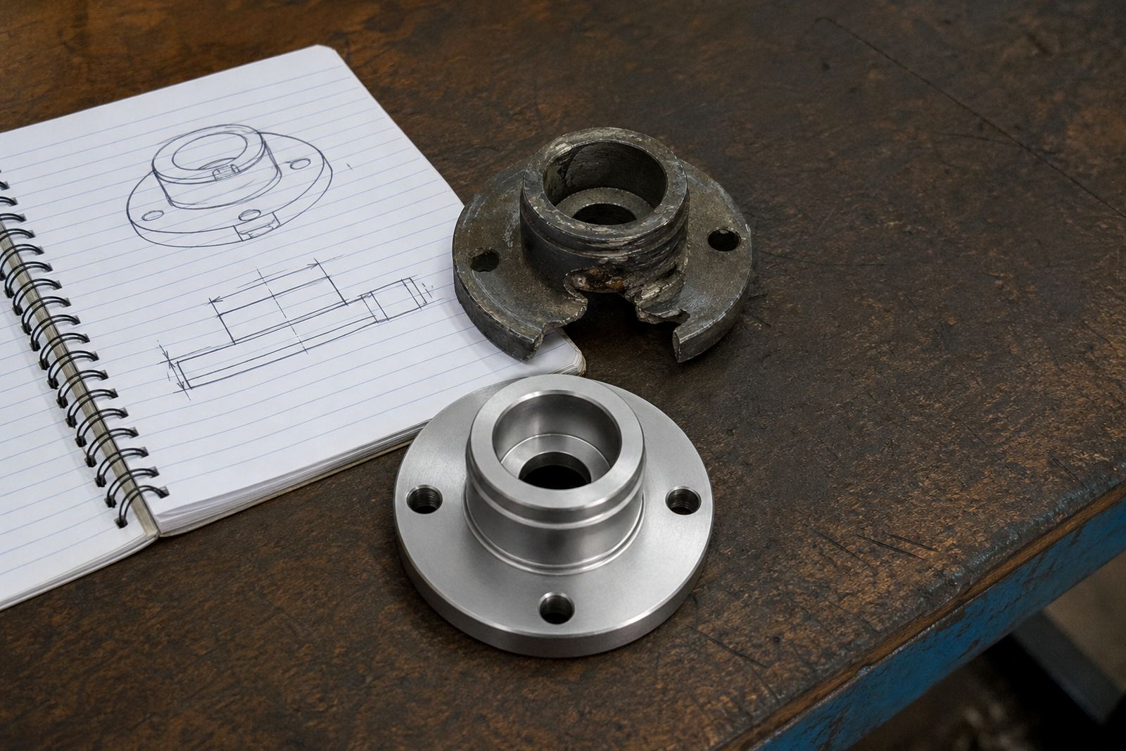
When a CNC job comes in, the first pass is not about cutting metal, it is about understanding the drawing. Overall size, material call-up, thickness, hole positions, thread sizes and any critical faces all affect how the part is set up and machined. If the drawing is clear, a shop in Pinetown can quote and plan the job with fewer assumptions. If it is vague, the quotation has to allow for extra checking or clarification, and that can slow everything down.
For small-batch work, the drawing should show the exact revision, units, scale if relevant, and whether the part is for milling, turning or a combination of both. A flat plate, a shaft, and a bracket may all look simple at a glance but they demand different setups. A drawing that marks the functional features clearly helps the team decide what can be made in one operation and what needs a second setup.
- Part name and revision level
- Units in millimetres, unless stated otherwise
- Material specification and any heat treatment or coating notes
- Critical dimensions that affect fit or assembly
- Quantity, especially for repeat orders or sample parts
How tolerances change the way a part is made
Tolerances tell the machinist how much variation is allowed. A general tolerance on a non-critical dimension is one thing, but a tight fit between a bore and a shaft is another. The tighter the tolerance, the more careful the machining, measurement and handling must be. That can change the machine time, tool selection and inspection steps, especially on small batches where each part may need extra attention.
Not every dimension needs the same level of control. In many jobs the drawing should separate working dimensions from non-critical ones, so the shop knows where to focus. If a hole must accept a bearing, for example, that feature needs clearer tolerance guidance than a cover plate edge. If a drawing asks for very fine control across every dimension, it may be worth checking whether the same result can be achieved more practically through part optimisation. Sometimes a small drawing change makes the job easier without affecting function.
- Specify only the features that need tight control
- Mark fit-critical diameters, hole positions and face relationships
- Include geometric controls where alignment matters
- Keep general tolerances sensible for the material and process
Material notes that prevent expensive mistakes
Material choice affects machining behaviour, tool wear and final appearance. Aluminium, mild steel, stainless steel, brass and engineering plastics all behave differently under the cutter. A drawing that simply says metal is not enough. The machinist needs the exact material family, grade if known and whether the part is supplied as bar, plate, billet or tube. That matters even more when the part is for coastal use in Durban or Richards Bay, where corrosion resistance becomes part of the conversation.
Coastal humidity can also influence storage and handling before machining. Some materials mark easily, some oxidise fast and some need care during deburring or clamping. If a part will be used outdoors or near chemicals, the drawing should mention the intended environment so the material and finish can be discussed properly. For example, a bracket for a workshop near the harbour may need a very different material discussion than a dry indoor fitting in Johannesburg.
- State the exact material rather than a broad category
- Note if the material must resist corrosion, wear or heat
- Identify any material substitution rules, if allowed
- Include grain direction or surface condition where it matters
What matters for milling, turning and mixed parts
CNC milling and CNC turning read differently on paper. Milling drawings usually focus on pockets, slots, faces, edge breaks, hole patterns and datum relationships. Turning drawings focus on diameters, lengths, shoulders, grooves, threads and concentricity. When a component needs both processes, the drawing should make the primary datum and critical features obvious so the part can be held true through the different operations.
A simple sketch can sometimes hide a difficult feature. A deep pocket may need a long reach tool, while a stepped shaft may need extra setups to keep the shoulders true. If a part will later be assembled, the machinist also needs to know which surfaces are functional and which are only cosmetic. That helps with part optimisation and keeps the discussion practical rather than theoretical.
- Use clear datums for faces, centres and axes
- Show thread callouts fully, including pitch and depth if needed
- Indicate surface finish where sealing or sliding occurs
- Mark any sharp edges that must be broken or left as-machined
Inspection notes that save time during sign-off
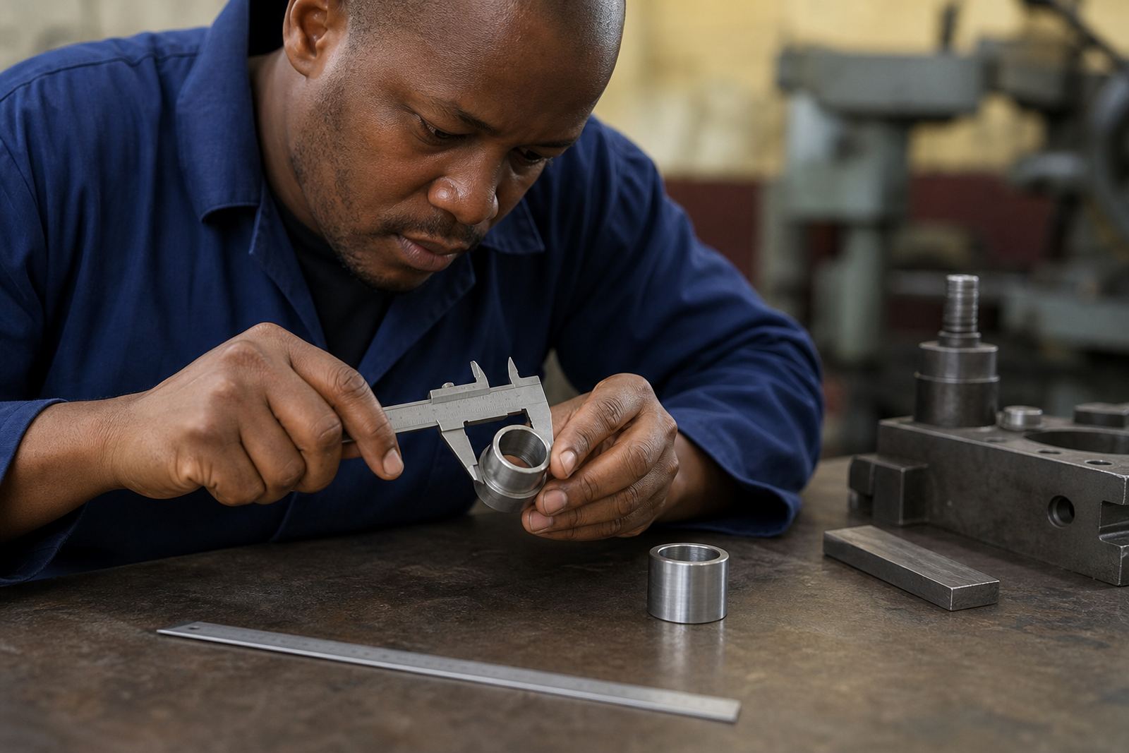
Inspection is easier when the drawing shows what must be checked and how important each feature is. If a component is going into assembly, the team may need to confirm hole spacing, perpendicular faces, thread engagement or bore size before release. A drawing that highlights these points helps with inspection reporting and reduces confusion later. It also helps when a sample part has to be remade because the intended fit was not confirmed early enough.
For repeated work, a consistent drawing format makes life easier for everybody. If the same component is ordered again six months later, clear notes on the revision, any updates and the inspection points let the shop compare new work with the approved sample. That is especially useful for clients in Pinetown, Westmead and New Germany who need quick turnaround but still want the part checked before it leaves the floor.
- Identify dimensions that must be measured on every batch
- Note any assembly fit checks or mating parts
- State whether cosmetic marks are acceptable or not
- Include revision history when the drawing has changed
A local example from Pinetown to Johannesburg
Consider a small bracket job for a client in Johannesburg who needs a run of parts for a machine frame. The basic shape may seem straightforward, but the drawing can still create questions. If the holes are not dimensioned from the right datum, the frame may not line up. If the material is not stated clearly, the machinist could quote on the wrong stock size. If the drawing does not say whether the edges must be de-burred or rounded, the final part may not suit the assembly. Small details like these affect machining, fit and delivery planning.
That is why a proper drawing review is part of the service before production starts. It helps identify missing notes, suggest practical changes, and keep the quotation conversation grounded in how the part will actually be made. In a job shop setting, that saves time for everyone and reduces the risk of repeat work that should have been avoided in the first place.
For businesses across Durban, Pietermaritzburg, Richards Bay and surrounding areas, clear drawings make small-batch CNC work easier to plan. In a place like Pinetown, where jobs often need quick coordination around power interruptions, transport timing and municipal delivery windows, clarity on paper matters just as much as the machine setup.