Why a clean drawing matters before the first chip is cut
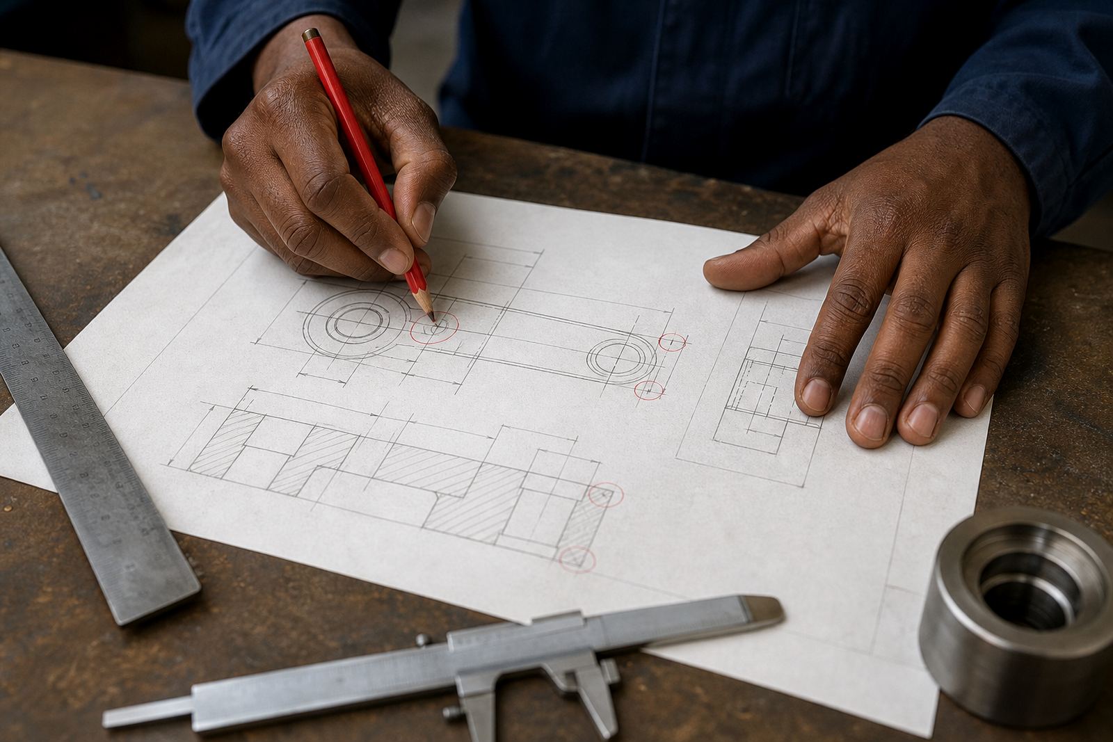
In CNC milling and turning, the drawing is the starting point for almost every decision. It tells the machinist what the part must look like, where features sit, which faces matter most, and what can be accepted without argument. If the drawing is vague, the job usually becomes slower and more expensive because the workshop has to stop and ask questions before work can begin.
For small batch production, that effect is even stronger. There is less room to hide a mistake across large quantities, so the first part has to be right and the next one must match it. A clear drawing helps with material selection, tool choice, workholding and inspection planning. It also helps avoid rework when a part has to fit with an existing assembly or line up with a second component made elsewhere.
At PME CNC Machining in Pinetown, we often see that the best jobs are not the flashiest. They are simply the ones where the drawing makes sense, the important features are marked clearly, and the finish requirements are stated properly. That saves everyone time, whether the part is going to Durban, Richards Bay or Johannesburg.
The most common drawing mistakes that cause hold ups
Some drawing problems come up again and again. None of them are unusual, but each one can slow the job or create avoidable questions if it is not corrected early.
- Missing dimensions on holes, slots, steps or edge details
- Tolerances shown on some features but not on others that matter just as much
- Conflicting dimensions, for example one view saying one size while another says something different
- No clear note on whether measurements are in millimetres, or if thread sizes are imperial or metric
- Surface finish requirements that are left out or written too loosely
- No indication of the material grade, temper or stock form needed
- Unsure revision status, where an old drawing and updated sketch are both in circulation
Even a small omission can cause a stop-start job. If a machinist has to guess the depth of a pocket or the position of a drilled hole, that guess is not acceptable. It is better to pause and confirm than to make a part that does not fit.
Tolerances need to be practical, not just tight
One of the biggest drawing issues is when tolerances are written too tightly without a real need. Tight tolerances are sometimes essential, but not on every feature. If every dimension is treated like a critical one, the job can become unnecessarily difficult to machine and inspect. That can add time and cost without improving the part in any meaningful way.
A better approach is to mark only the dimensions that truly affect fit, alignment or function. A bearing seat, shaft fit or mating face may need close control, while a non-critical cover plate hole can often allow a little more movement. This is where proper tolerance guidance helps the customer and the workshop work together rather than against each other.
In practice, this means asking a few simple questions before release:
- Which dimensions affect assembly fit?
- Which features are cosmetic only?
- Does the part need to interchange with an existing component?
- Will the part be checked with gauges, calipers or a CMM style inspection routine?
On small-batch work, sensible tolerancing often makes the difference between a smooth run and a job that needs repeated setup checks.
Material notes should be specific enough for the shop floor
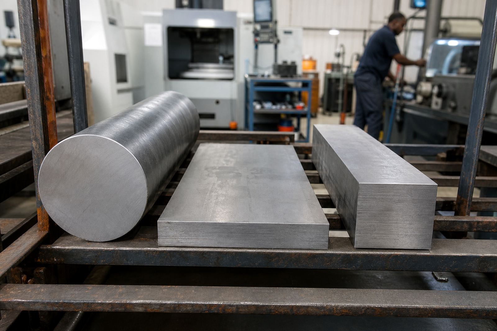
Material selection is another area where drawings often fall short. A note that simply says steel, aluminium or plastic may not be enough. Different grades and stock forms machine differently, react differently to heat, and perform differently in service. A part for coastal KwaZulu-Natal may need better corrosion resistance than a part used in a dry indoor setting, especially if it will sit near moisture or get handled often.
Where possible, the drawing should state the actual material type or at least the intended family and condition. That helps the machining team plan the job properly. It also avoids surprises if the component is meant to be anodised, plated, left raw or assembled with another part that must not seize.
- State the material clearly, not only as a broad category
- Note any required finish or coating
- Show if the part must stay free from burrs on certain edges
- Flag if the component will be exposed to heat, humidity or outdoor use
If the material is unclear, the workshop may need to pause and ask for clarification before ordering stock or setting up the machine. That is time lost before cutting even starts.
Old drawings and loose revisions create avoidable confusion
Revision control is easy to overlook, but it causes many drawing problems. A part can arrive with an older drawing, a saved PDF and a marked-up copy all floating around at the same time. If the team uses the wrong version, the finished component may no longer match the current assembly or customer request.
This is especially important when a part has already been updated after a sample remake or fit check. A small change to a hole position, thread depth or edge break can make the difference between a usable part and a rejected one. Good practice is to make the latest issue easy to identify and to remove older copies from circulation where possible.
For businesses in Durban or Johannesburg sending repeat work, this matters even more because the first job may have been approved months earlier. If the drawing changed since then, the workshop needs the latest information before repeat order support can be useful.
A Pinetown example: when a simple sketch needed a proper redraw
A local client once sent through a hand marked sketch for a small batch of turned parts with a milled flat and a drilled fixing point. The concept was clear enough, but the drawing did not show the correct datum, the hole centre was not fully defined, and the thread callout was missing. The part also had one face that needed to sit square in an assembly, but that requirement was never stated.
Before machining could begin, the drawing had to be reviewed and updated. Once the missing dimensions were added and the key fit surfaces identified, the job became straightforward. The customer got a better result and the workshop avoided making a part that would have needed rework or hand fitting. It was a good reminder that even a well meaning sketch can leave too much open to chance.
That kind of situation happens often on small-batch work across Pinetown, Westmead, New Germany and Umhlanga. The fix is usually simple: mark what matters, question what is unclear, and update the drawing before material is cut.
How to send a drawing that is ready for machining
If you want to keep a job moving, the drawing should answer the main workshop questions upfront. It does not need to be fancy. It needs to be clear, readable and complete enough for quoting, planning and inspection.
- Include all dimensions that define the part
- Mark critical tolerances and leave non-critical ones general where appropriate
- Specify material and finish requirements
- Show revision status and date where possible
- Add notes for assembly fit, burr control or special handling
- Keep sketches, PDFs and model files aligned so there is no conflict
When a drawing is clean, the job usually moves faster through drawing review, prototype planning, batch planning and inspection reporting. That matters for businesses that need reliable small-batch parts without unnecessary back-and-forth. If a drawing needs checking before machining starts, it is better to catch that early than to discover it after the first part is already on the machine.