Start With the Features That Control Fit
When a part is being checked, the first question is simple: which features make the part work? On a machined component that might be a bore, shaft diameter, hole pattern, face-to-face distance, thread, keyway or mounting plane. If those features are right, the rest of the inspection usually becomes much easier.
For small-batch work in Pinetown, Durban, Pietermaritzburg, Richards Bay and Johannesburg, it helps to mark the drawing before inspection begins. Circle the dimensions that affect assembly, movement, sealing or alignment. Those are the inspection points that deserve the first measurement, not every cosmetic edge or non-critical corner.
- Identify the datum surfaces or centres that the part is built from
- Mark any size that affects fit with another part
- Check features that can cause rejection later, such as threaded holes or seal faces
- Separate functional checks from appearance checks
Use the Drawing to Rank Critical Dimensions
A good drawing review tells you where the real risk sits. Look for tight tolerances, repeated dimensions, positional callouts and any note that affects the whole part. If a feature is called up more than once or appears in an assembly interface, it usually deserves special attention. This is where tolerance guidance helps, because not every dimension carries the same weight.
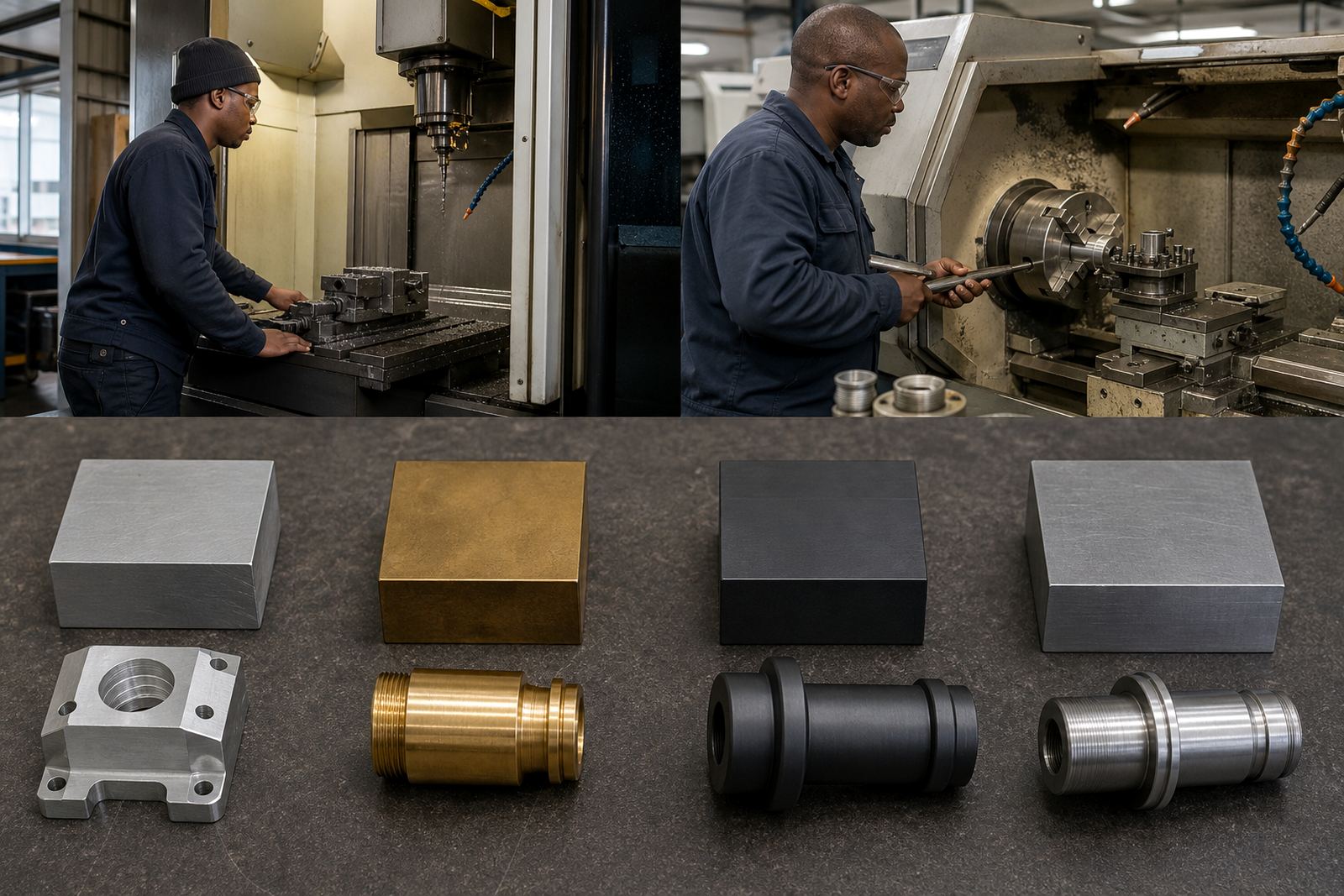
For turned parts, diameter, concentricity and end face position often matter most. For milled parts, flatness, hole location, slot width and pocket depth usually come first. If the part has both milling and turning operations, check the transition points carefully. A minor offset on one feature can throw off the next operation and create a fit problem later on, so it pays to inspect in the right order.
- Read the general tolerance note before measuring anything
- Look for dimensions tied to assembly or sealing
- Check positional accuracy on hole sets and machined patterns
- Confirm which surfaces were used as reference points during machining
Check Milling Features in the Right Order
On CNC milled parts, start with the faces that define the part size, then move to holes, slots and pockets. Flat surfaces tell you whether the part is sitting correctly in the machine and whether secondary cuts stayed true. If a part has a pocket or recess, measure depth as well as width because both can affect the final fit.
It is also worth checking edge conditions. Chamfers, radii and deburring may seem minor, but sharp edges can prevent assembly or damage cables, seals and operators hands. In coastal areas like Durban and Umhlanga, light surface rust can appear quickly if parts are left unprotected, so inspect surface condition after machining and before packing. A clean part on the bench is easier to read than one covered in swarf or oily fingerprints.
- Face-to-face size
- Hole diameter and hole location
- Slot width and slot depth
- Pocket depth, wall condition and edge break
- Flatness of contact surfaces
Check Turning Features That Decide Fit
For CNC turned components, the main inspection points usually sit on the outside diameter, inside diameter, shoulders and thread forms. If a shaft runs in a bearing or a bore mates with a housing, the diameter and surface finish matter more than cosmetic marks on non-working areas. Shoulders should be checked for position because they control where the part stops in assembly.
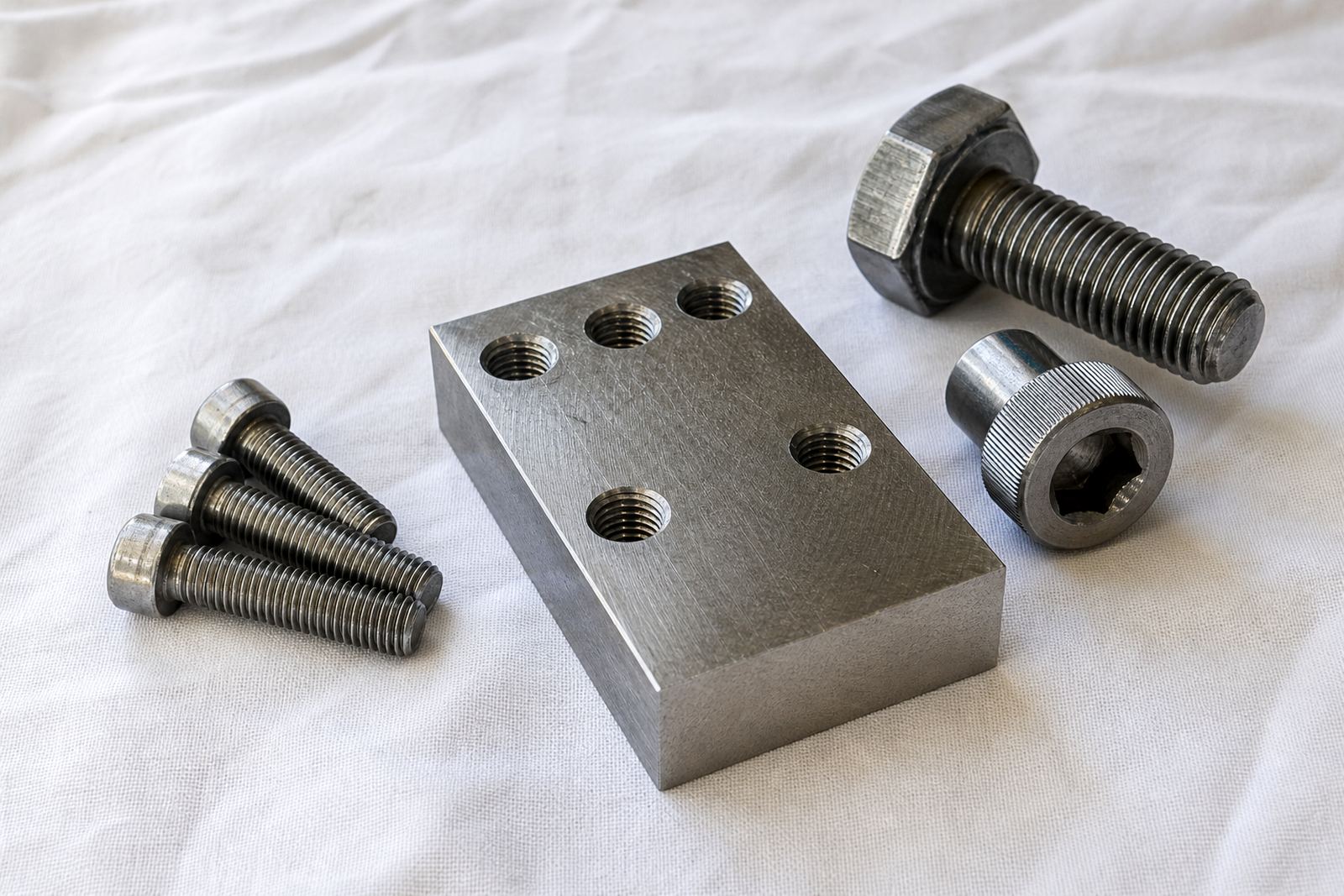
Threaded features need a practical fit check, not only a visual look. Confirm thread class, engagement length and whether the thread starts cleanly. If the part includes grooves, undercuts or seal lands, those areas should be inspected too because small errors can affect sealing and running clearance. On small batches, one rushed setup can create a whole stack of issues, so measuring the critical turn points early saves time.
- Outside diameter and inside diameter
- Shoulder length and face position
- Thread start, thread length and fit
- Groove width, groove depth and seal land size
- Roundness or runout where the application needs it
Use Simple Tools and a Repeatable Routine
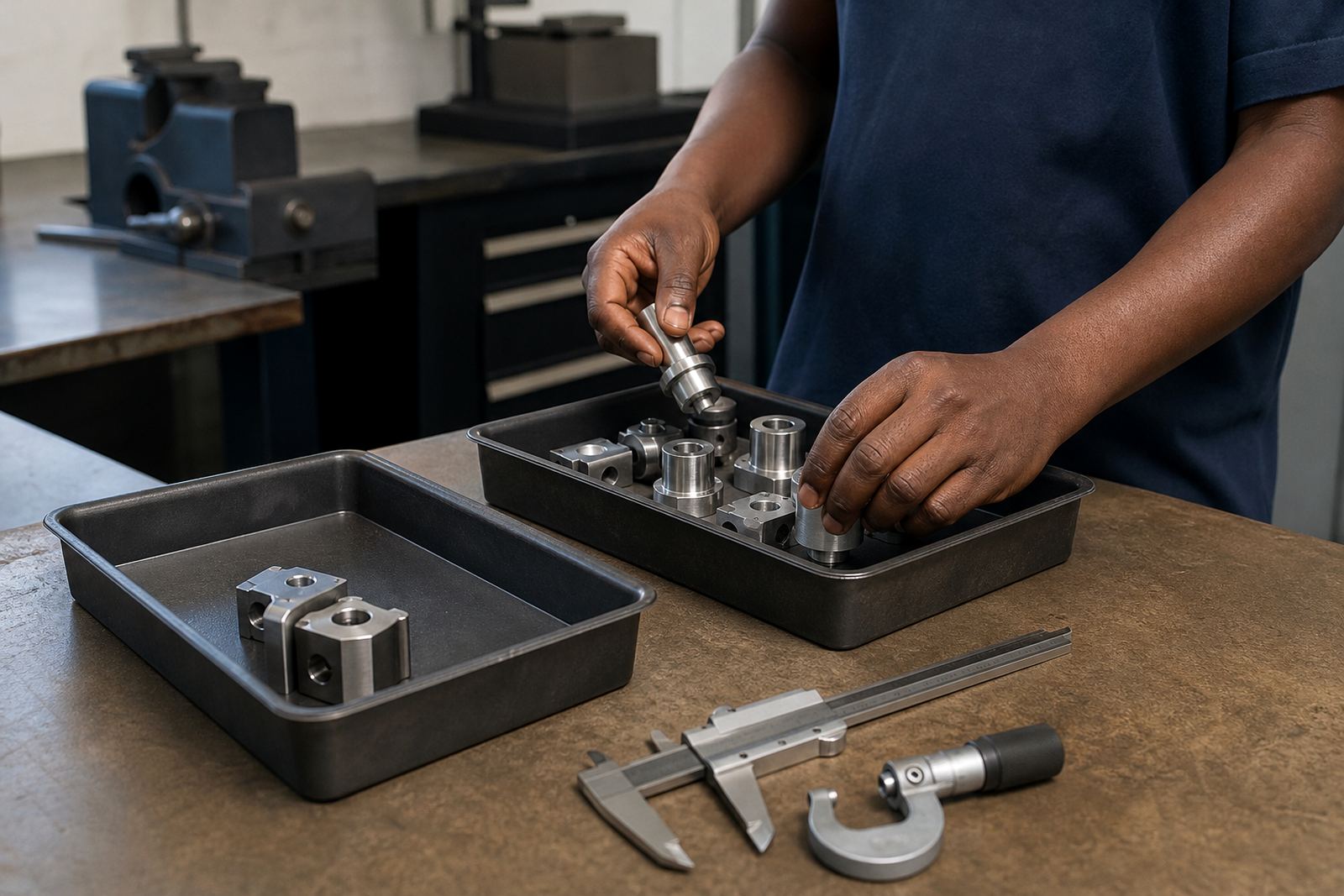
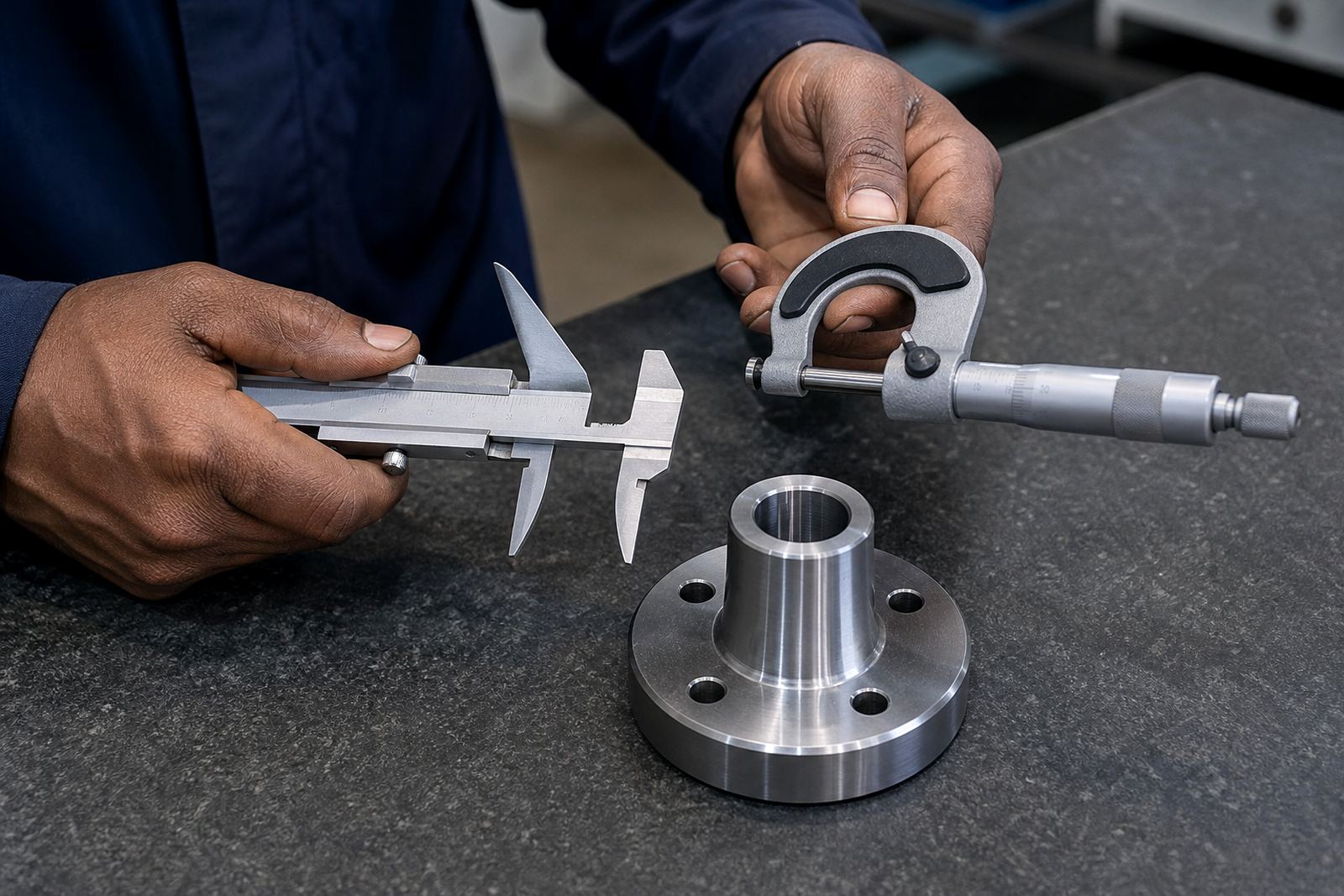
Inspection only works when the method stays the same from part to part. Use the right tool for the feature and keep the sequence consistent. A vernier caliper is fine for many general checks, but tighter features usually need better tooling and a calmer hand. Gauge pins, micrometers, height checks and surface plates all have their place, depending on the geometry.
It helps to create a short routine: first article, in-process sample, final check, then packing check. If a batch is being remade or updated after a drawing change, compare the new sample against the previous approved part and note what has changed. That makes repeat order support much easier and helps catch small shifts before they become a problem.
- Use the same measuring method for each batch
- Check parts at the same stage every time
- Record the tool used and the reading taken
- Separate acceptable variation from out-of-tolerance features
Record What Matters for Assembly and Repeat Orders
Inspection records should do more than say pass or fail. They should show which dimensions were checked, what the acceptance point was and whether the part needed any drawing updates or fit adjustments. This is especially useful on small-batch jobs where the next order may be months later and the original setup notes need to be clear.
Good records also help with assembly fit checks. If a component must line up with another machined part, note the mating feature and any special condition such as clearance, interference or alignment requirement. For clients across South Africa, from Westmead and New Germany through to Johannesburg, that paper trail makes communication easier and cuts down on back-and-forth when the next batch is placed.
- List the critical dimensions checked
- Note any feature that affects assembly or sealing
- Record deviations, corrections and remake actions
- Keep sample part notes with the job file