Start With the Dimensions That Affect Fit
Not every size on a drawing needs the same level of control. The first step is to separate critical dimensions from general ones. Critical dimensions are the sizes that affect assembly, bearing fit, shaft location, sealing, alignment or movement. General dimensions are the ones that only shape the part and can usually carry a wider limit.
For small-batch work in Pinetown and across KwaZulu-Natal, that distinction helps a lot. A part with too many tight dimensions can become slower to machine and harder to inspect, while a drawing with clear priorities is easier to plan. We look at how the part will be used, whether it must fit into a mating component and whether the customer needs repeatability from batch to batch.
- Mark the bore, shaft, face or slot that controls the function
- Identify which features must align during assembly
- Leave non-critical cosmetic sizes with practical limits
How Milling and Turning Affect Tolerance Choices
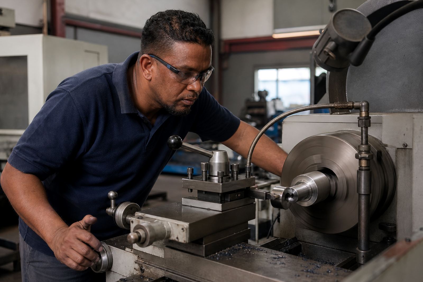
CNC milling and turning each suit different features. Turning is generally used for round parts such as shafts, spacers, bushes and stepped diameters. Milling is better for flats, pockets, slots, drilled patterns and shaped profiles. The method matters because the geometry affects how the tool reaches the cut, how the part is held and how much variation can build up across the job.
On a turned part, concentricity and diameter control often matter more than the outer shape. On a milled part, flatness, position and squareness can be the deciding factors. If a design mixes both methods, the tolerance stack-up should be checked carefully. A hole pattern may line up in the machine, but if the face is out or the stock varies too much, the final fit can still be off.
- Round parts usually need focus on diameter, concentricity and face location
- Milled parts often need attention on position, depth and perpendicularity
- Mixed parts need a full review of how one feature affects the next
Material Choice Changes What Is Sensible
Material selection has a real effect on tolerance planning. Aluminium is generally easier to machine and can suit tighter size control on many features. Mild steel and stainless steel may need slower cutting and careful handling to manage heat, tool wear and movement in the part. Plastics can behave differently again, especially on thin walls or long slender sections where the material may flex or creep.
Coastal humidity around Durban and Umhlanga can also matter when parts are stored before assembly. Some materials can oxidise or change slightly if left unprotected, so the tolerance and finish should suit the intended environment. If a part will be used near the coast, in a workshop or in a plant with washdown, we take that into account during drawing review and material selection.
- Choose material based on load, corrosion risk and service environment
- Check whether thin sections may distort during machining
- Allow for post-machining handling, storage and assembly conditions
A Practical Way to Set Tolerances
The best tolerance is the one that protects function without making the part harder than necessary to produce. Tight limits should be reserved for features that truly need them. Wider limits are often acceptable on non-fitting surfaces, support faces or cover plates. Good tolerance guidance starts with the function of the part and ends with a drawing that can be made and checked sensibly.
We often suggest a step-by-step review before production begins. That review can help reduce guesswork and avoid drawing revisions after the first sample. If a dimension is too tight for the material or the batch size, it may be better to change the fit type, adjust the mating part or add a simple datum reference. A sensible drawing saves time later and keeps the job moving, even when load-shedding interrupts the day and production has to be planned around it.
- Use tight limits only where function depends on them
- Reference dimensions from clear datums where possible
- Review the mating part, not just the drawing in isolation
What We Check Before Cutting the First Batch
Before production starts, PME CNC Machining can review the drawing for manufacturability and fit. That review usually covers the critical dimensions, stock allowance, tool access, clamping points and whether the tolerances suit the chosen material. If needed, we can suggest drawing updates or a sample part remake so the part works properly before the full batch is released.
This is especially useful for small-batch work where each piece matters and there may not be a large allowance for trial and error. Clients from Pinetown, Westmead, New Germany, Pietermaritzburg, Richards Bay and Johannesburg often need parts that fit the first time because the downstream assembly or repair slot is fixed. A clear plan at the start can prevent delays later on.
- Drawing Review and Tolerance Guidance
- Prototype Planning and Part Optimisation
- Sample Part Remake and Drawing Updates
Inspection Reporting and Repeat Order Support
Once parts are machined, inspection should confirm the dimensions that matter most. That may include key diameters, hole positions, step heights, thicknesses or face-to-face sizes. For repeat orders, it helps to keep the same datum scheme and the same inspection focus so the next batch matches the previous one as closely as possible.
We support repeat order work for clients who need ongoing small-batch supply. If a fitting issue appears after installation, we can look at the measured part and compare it with the intended drawing. Sometimes the answer is a tolerance change, sometimes it is a small design adjustment and sometimes the issue comes from the mating component rather than the machined part itself. Either way, clear inspection notes make the next job easier.
- Keep the same critical dimensions on repeat jobs
- Record any fit issues before changing the drawing
- Use inspection notes to guide the next batch